

Fabrication
CNC
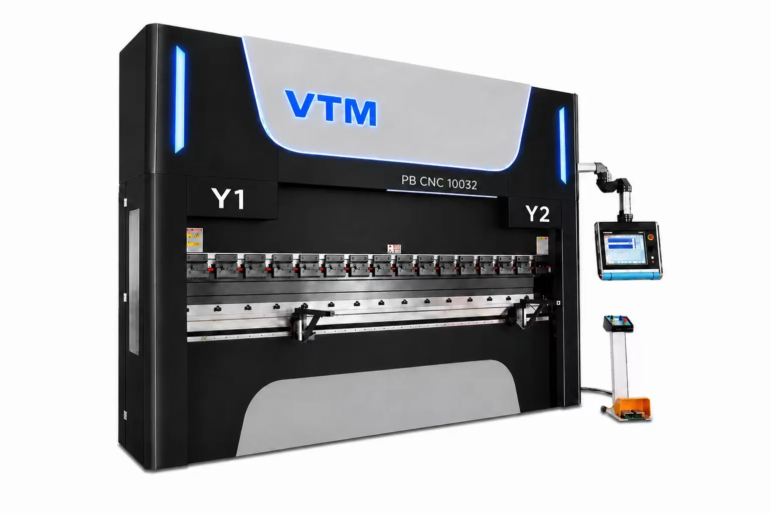
Press Brake
Two drive platforms — hydraulic single machines from 63 to 1600 tons for heavy plate, and servo electric tandem pairs from 160 to 800 tons per machine for synchronized bending up to 16 m.
Product Line
Choose Your Drive Type
Two press brake platforms — hydraulic for single-machine high tonnage and heavy plate, and servo electric tandem pairs for synchronized bending of long, heavy parts beyond single-machine capacity.
 1 / 3
1 / 3Hydraulic Series
26 hydraulic press brake configurations from 63 T up to 1600 T, with bending lengths from 2.5 m to 8 m. Dual-cylinder electrohydraulic synchronization, dual-motor drive on heavy frames (≥ 800 T), and hydraulic auto-crowning compensate for ram deflection in real time.
Best for
- Tonnage from 63 T up to 1600 T
- Bed lengths from 2.5 m to 8 m
- Throat depth up to 600 mm
- Heavy plate and structural fabrication
Technical Specifications
Hydraulic Series — Full Specs
1600T / 6000
16000
Nominal Force (kN)
6000 mm
Bending Length
4800 mm
Pole Distance
500 mm
Throat Depth
400 mm
Slider Travel
800 mm
Worktable Height
800 mm
Die Loading Height
2×55 kW
Main Motor
800 mm
Back Gauge X Travel
100 mm/s
Back Gauge X Speed
6500 × 3300 × 6500 mm
Dimensions (L × W × H)
1600T / 7000
16000
Nominal Force (kN)
7000 mm
Bending Length
5400 mm
Pole Distance
500 mm
Throat Depth
400 mm
Slider Travel
800 mm
Worktable Height
800 mm
Die Loading Height
2×55 kW
Main Motor
800 mm
Back Gauge X Travel
100 mm/s
Back Gauge X Speed
7500 × 3300 × 7000 mm
Dimensions (L × W × H)
1600T / 8000
16000
Nominal Force (kN)
8000 mm
Bending Length
6400 mm
Pole Distance
500 mm
Throat Depth
400 mm
Slider Travel
800 mm
Worktable Height
800 mm
Die Loading Height
2×55 kW
Main Motor
800 mm
Back Gauge X Travel
100 mm/s
Back Gauge X Speed
8500 × 3300 × 8000 mm
Dimensions (L × W × H)
63T / 2500
630
Nominal Force (kN)
2500 mm
Bending Length
1900 mm
Pole Distance
350 mm
Throat Depth
150 mm
Slider Travel
800 mm
Worktable Height
380 mm
Die Loading Height
7.5 kW
Main Motor
600 mm
Back Gauge X Travel
100 mm/s
Back Gauge X Speed
3100 × 1450 × 2050 mm
Dimensions (L × W × H)
80T / 3200
800
Nominal Force (kN)
3200 mm
Bending Length
2600 mm
Pole Distance
350 mm
Throat Depth
200 mm
Slider Travel
800 mm
Worktable Height
380 mm
Die Loading Height
7.5 kW
Main Motor
600 mm
Back Gauge X Travel
100 mm/s
Back Gauge X Speed
3500 × 1550 × 2100 mm
Dimensions (L × W × H)
100T / 3200
1000
Nominal Force (kN)
3200 mm
Bending Length
2600 mm
Pole Distance
400 mm
Throat Depth
200 mm
Slider Travel
850 mm
Worktable Height
420 mm
Die Loading Height
7.5 kW
Main Motor
600 mm
Back Gauge X Travel
100 mm/s
Back Gauge X Speed
3500 × 1580 × 2400 mm
Dimensions (L × W × H)
160T / 3200
1600
Nominal Force (kN)
3200 mm
Bending Length
2600 mm
Pole Distance
400 mm
Throat Depth
200 mm
Slider Travel
920 mm
Worktable Height
420 mm
Die Loading Height
11 kW
Main Motor
600 mm
Back Gauge X Travel
100 mm/s
Back Gauge X Speed
3500 × 1650 × 2500 mm
Dimensions (L × W × H)
200T / 3200
2000
Nominal Force (kN)
3200 mm
Bending Length
2600 mm
Pole Distance
400 mm
Throat Depth
200 mm
Slider Travel
920 mm
Worktable Height
420 mm
Die Loading Height
11 kW
Main Motor
600 mm
Back Gauge X Travel
100 mm/s
Back Gauge X Speed
3500 × 1680 × 2550 mm
Dimensions (L × W × H)
250T / 3200
2500
Nominal Force (kN)
3200 mm
Bending Length
2600 mm
Pole Distance
400 mm
Throat Depth
200 mm
Slider Travel
920 mm
Worktable Height
420 mm
Die Loading Height
18.5 kW
Main Motor
600 mm
Back Gauge X Travel
100 mm/s
Back Gauge X Speed
3500 × 1700 × 2600 mm
Dimensions (L × W × H)
320T / 3200
3200
Nominal Force (kN)
3200 mm
Bending Length
1600 mm
Pole Distance
400 mm
Throat Depth
200 mm
Slider Travel
950 mm
Worktable Height
420 mm
Die Loading Height
18.5 kW
Main Motor
600 mm
Back Gauge X Travel
100 mm/s
Back Gauge X Speed
3500 × 1800 × 2730 mm
Dimensions (L × W × H)
400T / 4000
4000
Nominal Force (kN)
4000 mm
Bending Length
3100 mm
Pole Distance
400 mm
Throat Depth
200 mm
Slider Travel
800 mm
Worktable Height
420 mm
Die Loading Height
30 kW
Main Motor
800 mm
Back Gauge X Travel
100 mm/s
Back Gauge X Speed
4300 × 2080 × 2730 mm
Dimensions (L × W × H)
500T / 5000
5000
Nominal Force (kN)
5000 mm
Bending Length
4000 mm
Pole Distance
500 mm
Throat Depth
300 mm
Slider Travel
800 mm
Worktable Height
600 mm
Die Loading Height
37 kW
Main Motor
800 mm
Back Gauge X Travel
100 mm/s
Back Gauge X Speed
5400 × 2525 × 4600 mm
Dimensions (L × W × H)
500T / 6000
5000
Nominal Force (kN)
6000 mm
Bending Length
4800 mm
Pole Distance
500 mm
Throat Depth
300 mm
Slider Travel
800 mm
Worktable Height
600 mm
Die Loading Height
37 kW
Main Motor
800 mm
Back Gauge X Travel
100 mm/s
Back Gauge X Speed
6500 × 2525 × 4200 mm
Dimensions (L × W × H)
500T / 7000
5000
Nominal Force (kN)
7000 mm
Bending Length
5400 mm
Pole Distance
500 mm
Throat Depth
300 mm
Slider Travel
800 mm
Worktable Height
600 mm
Die Loading Height
91 kW
Main Motor
800 mm
Back Gauge X Travel
100 mm/s
Back Gauge X Speed
7500 × 2525 × 4900 mm
Dimensions (L × W × H)
600T / 5000
6000
Nominal Force (kN)
5000 mm
Bending Length
4000 mm
Pole Distance
500 mm
Throat Depth
300 mm
Slider Travel
800 mm
Worktable Height
600 mm
Die Loading Height
45 kW
Main Motor
800 mm
Back Gauge X Travel
100 mm/s
Back Gauge X Speed
5500 × 2450 × 4500 mm
Dimensions (L × W × H)
600T / 6000
6000
Nominal Force (kN)
6000 mm
Bending Length
4800 mm
Pole Distance
500 mm
Throat Depth
300 mm
Slider Travel
800 mm
Worktable Height
600 mm
Die Loading Height
45 kW
Main Motor
800 mm
Back Gauge X Travel
100 mm/s
Back Gauge X Speed
6500 × 2450 × 5100 mm
Dimensions (L × W × H)
600T / 7000
6000
Nominal Force (kN)
7000 mm
Bending Length
5400 mm
Pole Distance
500 mm
Throat Depth
300 mm
Slider Travel
800 mm
Worktable Height
600 mm
Die Loading Height
45 kW
Main Motor
800 mm
Back Gauge X Travel
100 mm/s
Back Gauge X Speed
7500 × 2450 × 5200 mm
Dimensions (L × W × H)
800T / 6000
8000
Nominal Force (kN)
6000 mm
Bending Length
5000 mm
Pole Distance
600 mm
Throat Depth
400 mm
Slider Travel
800 mm
Worktable Height
800 mm
Die Loading Height
2×30 kW
Main Motor
800 mm
Back Gauge X Travel
100 mm/s
Back Gauge X Speed
6500 × 2750 × 5300 mm
Dimensions (L × W × H)
800T / 7000
8000
Nominal Force (kN)
7000 mm
Bending Length
5400 mm
Pole Distance
600 mm
Throat Depth
400 mm
Slider Travel
800 mm
Worktable Height
800 mm
Die Loading Height
2×30 kW
Main Motor
800 mm
Back Gauge X Travel
100 mm/s
Back Gauge X Speed
7500 × 2750 × 5500 mm
Dimensions (L × W × H)
800T / 8000
8000
Nominal Force (kN)
8000 mm
Bending Length
6400 mm
Pole Distance
600 mm
Throat Depth
400 mm
Slider Travel
800 mm
Worktable Height
800 mm
Die Loading Height
2×30 kW
Main Motor
800 mm
Back Gauge X Travel
100 mm/s
Back Gauge X Speed
8600 × 2750 × 5900 mm
Dimensions (L × W × H)
1000T / 6000
10000
Nominal Force (kN)
6000 mm
Bending Length
4800 mm
Pole Distance
600 mm
Throat Depth
400 mm
Slider Travel
800 mm
Worktable Height
800 mm
Die Loading Height
2×37 kW
Main Motor
800 mm
Back Gauge X Travel
100 mm/s
Back Gauge X Speed
6500 × 2800 × 5600 mm
Dimensions (L × W × H)
1000T / 7000
10000
Nominal Force (kN)
7000 mm
Bending Length
5400 mm
Pole Distance
600 mm
Throat Depth
400 mm
Slider Travel
800 mm
Worktable Height
800 mm
Die Loading Height
2×37 kW
Main Motor
800 mm
Back Gauge X Travel
100 mm/s
Back Gauge X Speed
7500 × 2800 × 5800 mm
Dimensions (L × W × H)
1000T / 8000
10000
Nominal Force (kN)
8000 mm
Bending Length
6400 mm
Pole Distance
600 mm
Throat Depth
400 mm
Slider Travel
800 mm
Worktable Height
800 mm
Die Loading Height
2×37 kW
Main Motor
800 mm
Back Gauge X Travel
100 mm/s
Back Gauge X Speed
8500 × 2900 × 6100 mm
Dimensions (L × W × H)
1200T / 6000
12000
Nominal Force (kN)
6000 mm
Bending Length
5000 mm
Pole Distance
600 mm
Throat Depth
400 mm
Slider Travel
800 mm
Worktable Height
800 mm
Die Loading Height
2×45 kW
Main Motor
800 mm
Back Gauge X Travel
100 mm/s
Back Gauge X Speed
6500 × 3100 × 5850 mm
Dimensions (L × W × H)
1200T / 7000
12000
Nominal Force (kN)
7000 mm
Bending Length
5400 mm
Pole Distance
600 mm
Throat Depth
400 mm
Slider Travel
800 mm
Worktable Height
800 mm
Die Loading Height
2×45 kW
Main Motor
800 mm
Back Gauge X Travel
100 mm/s
Back Gauge X Speed
7500 × 3100 × 6550 mm
Dimensions (L × W × H)
1200T / 8000
12000
Nominal Force (kN)
8000 mm
Bending Length
6400 mm
Pole Distance
600 mm
Throat Depth
400 mm
Slider Travel
800 mm
Worktable Height
800 mm
Die Loading Height
2×45 kW
Main Motor
800 mm
Back Gauge X Travel
100 mm/s
Back Gauge X Speed
8500 × 3100 × 7150 mm
Dimensions (L × W × H)
1600T / 6000
16000
Nominal Force (kN)
6000 mm
Bending Length
4800 mm
Pole Distance
500 mm
Throat Depth
400 mm
Slider Travel
800 mm
Worktable Height
800 mm
Die Loading Height
2×55 kW
Main Motor
800 mm
Back Gauge X Travel
100 mm/s
Back Gauge X Speed
6500 × 3300 × 6500 mm
Dimensions (L × W × H)
1600T / 7000
16000
Nominal Force (kN)
7000 mm
Bending Length
5400 mm
Pole Distance
500 mm
Throat Depth
400 mm
Slider Travel
800 mm
Worktable Height
800 mm
Die Loading Height
2×55 kW
Main Motor
800 mm
Back Gauge X Travel
100 mm/s
Back Gauge X Speed
7500 × 3300 × 7000 mm
Dimensions (L × W × H)
1600T / 8000
16000
Nominal Force (kN)
8000 mm
Bending Length
6400 mm
Pole Distance
500 mm
Throat Depth
400 mm
Slider Travel
800 mm
Worktable Height
800 mm
Die Loading Height
2×55 kW
Main Motor
800 mm
Back Gauge X Travel
100 mm/s
Back Gauge X Speed
8500 × 3300 × 8000 mm
Dimensions (L × W × H)
63T / 2500
630
Nominal Force (kN)
2500 mm
Bending Length
1900 mm
Pole Distance
350 mm
Throat Depth
150 mm
Slider Travel
800 mm
Worktable Height
380 mm
Die Loading Height
7.5 kW
Main Motor
600 mm
Back Gauge X Travel
100 mm/s
Back Gauge X Speed
3100 × 1450 × 2050 mm
Dimensions (L × W × H)
80T / 3200
800
Nominal Force (kN)
3200 mm
Bending Length
2600 mm
Pole Distance
350 mm
Throat Depth
200 mm
Slider Travel
800 mm
Worktable Height
380 mm
Die Loading Height
7.5 kW
Main Motor
600 mm
Back Gauge X Travel
100 mm/s
Back Gauge X Speed
3500 × 1550 × 2100 mm
Dimensions (L × W × H)
100T / 3200
1000
Nominal Force (kN)
3200 mm
Bending Length
2600 mm
Pole Distance
400 mm
Throat Depth
200 mm
Slider Travel
850 mm
Worktable Height
420 mm
Die Loading Height
7.5 kW
Main Motor
600 mm
Back Gauge X Travel
100 mm/s
Back Gauge X Speed
3500 × 1580 × 2400 mm
Dimensions (L × W × H)
Available Upgrades
Automatic Crowning Compensation
When pressing long parts, both the bed and ram flex under load, causing the center of the bend to angle differently than the ends. VTM press brakes include a hydraulic crowning system that pre-compensates the bed — raising it slightly at the center — so the bend angle stays consistent from end to end.

CNC Controllers
Two Controller Options
Both machines ship with a DELEM graphical CNC controller running real-time embedded Linux. Choose based on your shop's programming workflow and automation needs.
| Feature |  |  |
|---|---|---|
| Display | 15.6" TFT touch (1366 × 768) | 24" full touch (1920 × 1080, 32-bit color) |
| Operating System | Real-time embedded Linux | Real-time embedded Linux (multitasking) |
| Programming | 2D graphical (optional) + alphanumeric | 2D + 3D graphical programming & simulation |
| Programming features | Bend sequence · radius/bumping · one-page | Auto bend sequence · job list · DXF import · sequence optimization |
| 3D visualization | — | Real-scale 3D part simulation |
| Auto calculations | Force · allowance · crowning · bottoming · hemming | Force · allowance · crowning · developed length · bottoming · hemming |
| Angle correction | Learned angle correction database | Advanced learned angle correction database |
| Tooling support | Tool library (30 punches / 30 dies) | Graphical tool setup · segmentation visualization · tool library |
| Crowning control | CNC crowning | CNC crowning (automatic compensation available) |
| Connectivity | USB · optional network | Multiple network ports · USB · optional OPC-UA |
| File integration | — | DXF import (parts & tooling) |
| Automation | Auto bumping calculation | Auto sequence optimization · auto bumping · stock counter |
| Remote diagnostics | — | Yes — remote diagnostics + onboard analysis |
| Safety | Safety PLC interfacing (RS232) | Safety PLC interfacing |
| Protection / Weight | IP54 · ~7 kg | IP54 · ~14.5 kg housing / ~9 kg panel |
DA-53T
Best for shops that need a proven, fast DELEM interface on embedded Linux. Handles standard and complex bending with full auto-calculations, bumping, and CNC crowning.
DA-69S
Best for high-mix production, 3D part simulation, DXF-to-bend workflows, and shops that need sequence optimization and remote diagnostics.
4+1 to 8+1 Axis Back Gauge — Complex Parts, Simple Setup
X, R, Z1, and Z2 axes on the back gauge allow independent positioning of each finger — critical for flanges at multiple depths, offset bends, and parts that taper. Every back gauge position is stored in the part program and recalled automatically when you run the same job again.

See It Bend
Complex Parts, First-Part Accuracy
Video embed — insert YouTube or Cloudflare Stream URL
Configure
Build Your Machine
Tonnage
- 40T — light gauge sheet metal, up to 8 ft
- 80T — general fabrication
- 110T — structural profiles up to 10 ft
- 160T — heavy plate to 0.75"
- 220T — stainless and thick aluminum
- 400T — heavy structural fabrication
Tonnage selection depends on your thickest material, widest bend, and material tensile strength. VTM engineers will size correctly for your work.
Bending Length
- 98" (2500 mm)
- 118" (3000 mm)
- 157" (4000 mm)
- 197" (5000 mm)
- 236" (6000 mm)
Match to your longest standard sheet or profile. Longer beds require proportionally higher tonnage to maintain accuracy.
Tooling Package
- Standard European-style tooling set
- Amada-compatible tooling
- Auto tool change system (hydraulic)
- Wila precision tooling upgrade
Wila precision tooling offers clamping accuracy to ±0.001" — recommended for tight-tolerance aerospace and medical work.
All configurations available to order. Contact your VTM sales engineer for pricing and lead time on your specific build.
Technology
CNC Press Brake vs. Manual Press Brake
| Feature | CNC Press Brake | Manual Press Brake |
|---|---|---|
| Repeatability | ±0.01 mm | ±0.5 mm or worse |
| Setup time per job | 5–15 min (program recalled) | 30–60 min (manual trial and error) |
| 3D bend simulation | Yes — collision detection included | None |
| Back gauge | 4+1 to 8+1 axis CNC | Manual single-axis |
| Crowning compensation | Automatic | Manual shims (if available) |
| Operator skill required | Low — controller guides operator | High — experienced operator essential |
| Part-to-part consistency | Identical | Operator-dependent variation |
| Initial cost | Higher | Lower |
Get Pricing
Request a Quote
Tell us about your shop and the work you're doing. We'll respond with pricing, lead time, and recommended configuration within one business day.
- No obligation
- Response within 1 business day
- Speak directly with a machine specialist
Continue Exploring
Related Machines


Questions
Frequently Asked
VTM press brakes ship configured for standard European-style (Wila/Wilson) tooling, which is compatible with the majority of aftermarket tooling available in the US. Amada-style tool holders are available as a configuration option. If you have existing tooling you want to keep using, share the tooling profile with your VTM sales engineer before ordering — we'll confirm compatibility or recommend an adapter.
The graphic CNC controller uses a touchscreen interface with 3D part visualization. Most operators reach full programming proficiency within 2–3 days of training. DXF files from your CAD system can be imported directly — the controller auto-generates the bend sequence and calculates tonnage. VTM includes 2 days of on-site programming training with every machine.
Tonnage is determined by material type, thickness, tensile strength, and bend length. As a rough guideline for mild steel: 1" material over a 10-foot bend requires approximately 150 tons. Your VTM sales engineer will calculate the required tonnage for your specific jobs before recommending a machine. It is better to have more tonnage than you need — running a 110-ton machine at 40% capacity is more accurate and extends machine life compared to running at 95%.
Standard lead time is 10–14 weeks from confirmed order. VTM's installation team handles rigging coordination, leveling (precision-shimmed to 0.1 mm/m), hydraulic and electrical commissioning, and first-article verification bends. Installation typically takes 1–2 days depending on machine size. Operator and programming training follows immediately after commissioning.
The auto tool change system must be specified at time of order — it requires specific hydraulic provisions and ram geometry that cannot be retrofitted after manufacture. If there's any possibility you'll want it in the future, we recommend specifying it upfront. The productivity gain on high-mix production makes it one of the highest-ROI options available.
CNC Press Brake